OAK8X Module hardware installation
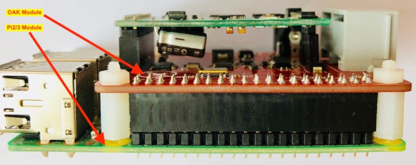
Insert the OAK8X module to a Raspberry Pi 2 or 3 board like below picture shows
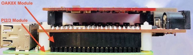
We provide 4 plastic screws, use them to fix the OAK board to Raspberry Pi board such as below shows

The finally looks like below

Until now, the OAK8X module installation is done, let us move to software installation.
OAK8X Module software installation
There are two ways to install the OAK8X module software, one uses our firmware get a quick try, other is you can compile whole things by yourself as the OAK8X module is open source designed.
Use our firmware
Download the SwitchPi OAK8x firmware – switchpi-oak8x-with-gui-1.0.1.imag.zip in here . The switchpi-oak8x firmware currently version is 1.0.1, built-in Asterisk-13.20 and Dahdi-2.11.1.
Put the downloaded firmware to a Linux distro PC, then following below steps to clone it to an 8G SD card (we strongly suggested to use a class 10 HC SD card such as below SanDisk one):

Insert micro SD card to your PC with a USB SD card adaptor, the Linux will recognized it like /dev/sda or /dev/sdb which depends on your OS how many drives, you can check it out with command “dmesg”, we are using the /dev/sdb in here.
root@oak:~/pitdm# unzip switchpi-oak8x-with-gui-1.0.1.img.zip
root@oak:~/pitdm# dd if=switchpi-oak8x-with-gui-1.0.1.img of=/dev/sdb bs=4M
Compile driver by yourself
Please follow the OAK8X module README.md to compile the driver, https://github.com/lixinswitchpi/oak8x
Power Up
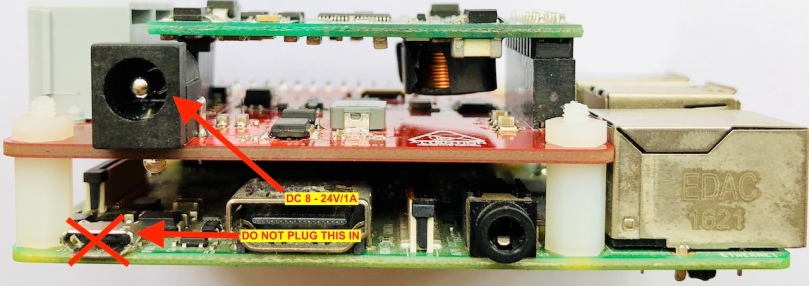
Remove the SD card from Linux PC and insert it to your Raspberry Pi 2/3 board, plug the 12V (or 9V 2A) power supply which is with your OAK module together when you received your order as below shows
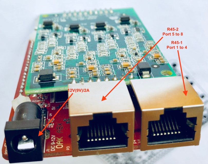
Please pay attention in here, as our OAK module feeds your Raspberry Pi power as well, thus you DO NOT require to insert the Raspberry Pi USB DC power supply anymore !!!
The default IP address is 192.168.4.98, you can ssh log into it with username “pi”, password “raspberry”.
[ 2049.193945] wc thunder exit
[ 2049.303202] I2S SETUP COMPLETE
[ 2049.316825] ENABLED I2S
[ 2049.316851] TDM bus clock synced with SwitchPi CPLD core!
[ 2049.802168] Module 0: Installed -- AUTO FXO (FCC mode)
[ 2050.002157] Module 1: Installed -- AUTO FXO (FCC mode)
[ 2050.202164] Module 2: Installed -- AUTO FXO (FCC mode)
[ 2050.402155] Module 3: Installed -- AUTO FXO (FCC mode)
[ 2052.574536] Module 4: Installed -- AUTO FXS/DPO
[ 2054.784501] Module 5: Installed -- AUTO FXS/DPO
[ 2056.914511] Module 6: Installed -- AUTO FXS/DPO
[ 2059.044523] Module 7: Installed -- AUTO FXS/DPO
[ 2059.044535] Found a Wildcard TDM: SwitchPi Thunder FXS/FXO (8 modules)
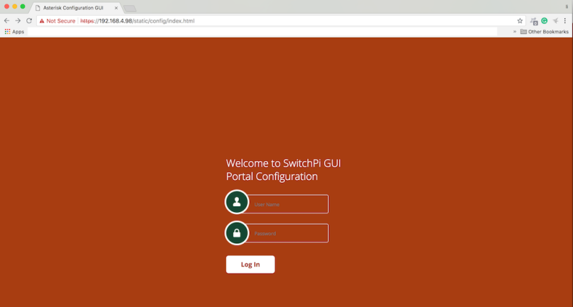
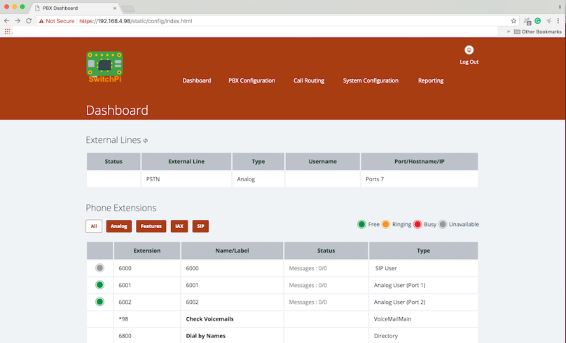
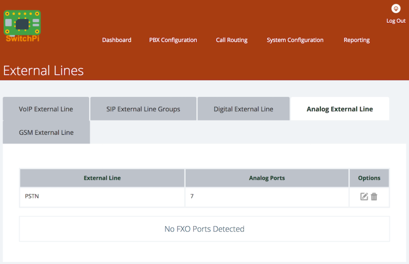
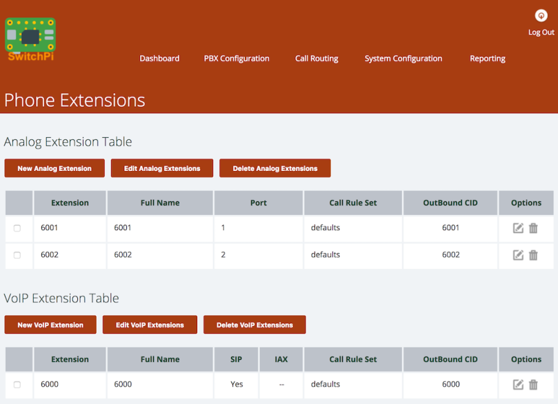
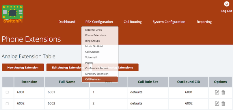
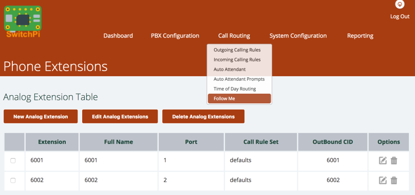
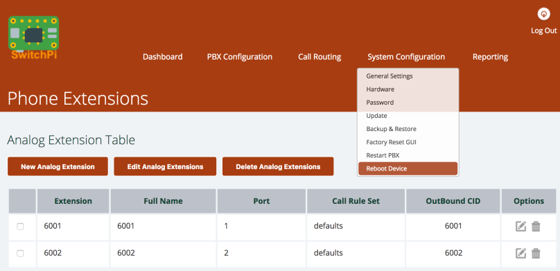
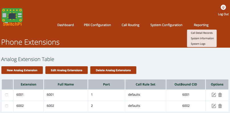
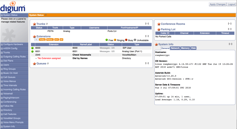
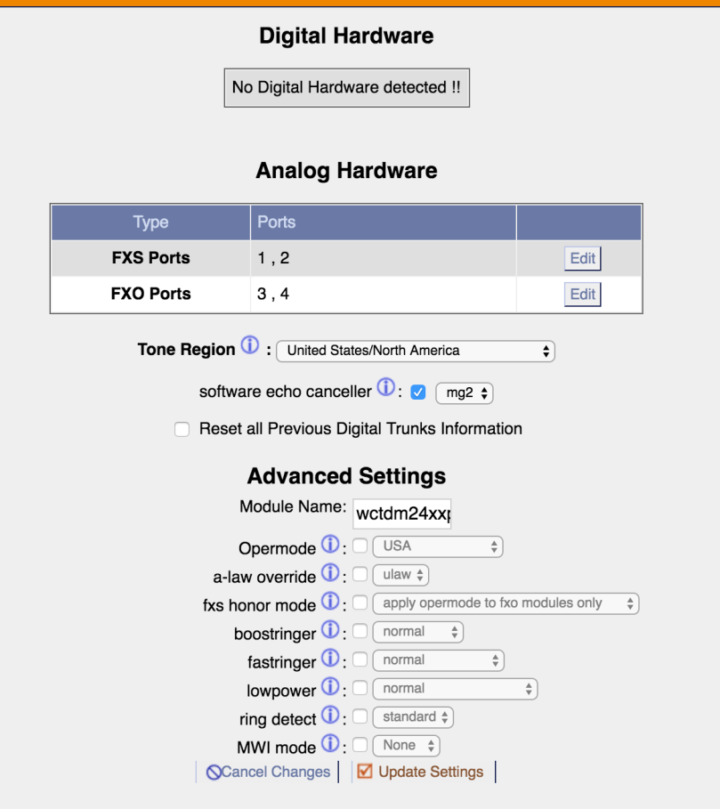
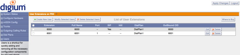
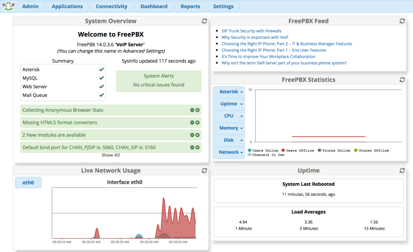
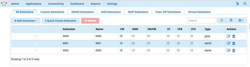
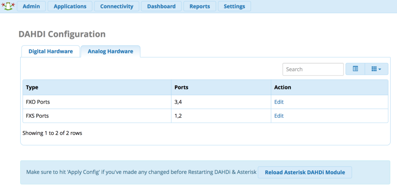
Now you can use your web browser to log into the GUI of SwitchPi to configure your OAK8X module, for the details, check it out in here. (The OAK8X SwitchPi GUI defaults IP address is 192.168.4.98)
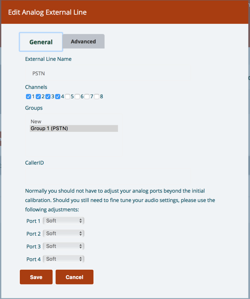
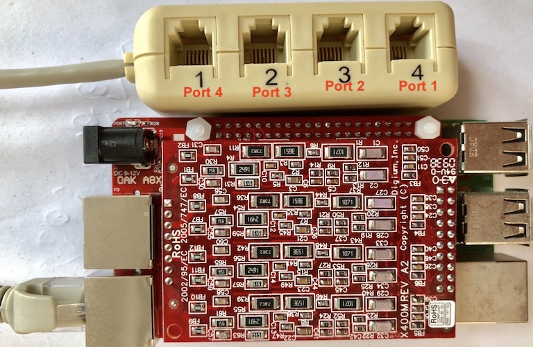
The RJ45 to RJ11 adaptor ports definition
Per the RJ45 manufacturer’s wire sequence changed, the correct RJ11 ports definition like below picture shows: